
1. Introduction
In the HVAC application, fresh outdoor air is supplied to the room/space for various reasons, such as:
- To maintain IAQ by diluting indoor pollutants such as carbon dioxide (CO₂), volatile organic compounds (VOCs), odors, and other contaminants.
- Pressurization
- Make-up air for exhaust (like kitchen, workshop etc.)
- Air for internally located equipment (Combustion air for internally located IC engines, air for compressor)
- Dilution of hazardous gases
- For cooling in mechanically and naturally ventilated rooms/spaces etc.
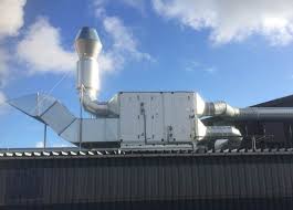
The required outdoor fresh air is sucked through the fresh air intake system (and mixed with room return air, if applicable, processed in the air handling equipment, as required) and supplied to the room/space.
After performing the above functions, the ventilation air is either relieved or extracted and exhausted safely, by exhaust system.
In this article, we will learn the factors to be considered when finalizing the location for the fresh air intake and exhaust in an HVAC system, to ensure system efficiency, safety, and compliance with regulations.
2. Key Considerations for Fresh Air Intake and Exhaust Placement
2.1 Fresh Air Intake Location
The intake should be located away from hazardous areas, including exhaust (such as hot, foul, smoke, combustion gases, pollutants, vents, etc.), relief vents operable windows, skylights, and doors.
It is essential to maintain the minimum separation distances as specified in project specifications, codes, standards, and local regulations. Refer to the “ASHRAE 62.1, Table 5-1 Air Intake Minimum Separation Distance”, for the minimum separation distance to be maintained between fresh air intake and exhaust, relief, plumbing/chimney vents, driveway, garage, truck loading area, bus parking, evaporative heat rejection exhaust/intake, and parking place. Refer to Appendix B2 for the minimum separation distance calculation and its methods (Simple method, velocity method, and concentration method). These methods can be used instead of Table 5-1. Refer to NFPA 45 for laboratory fume exhaust discharge location and the required separation distance.
In some projects, Computational Fluid Dynamics (CFD) analysis may be required for precise placement.
2.2 Placement of Intake and Exhaust
Avoid placing the intake and exhaust on the same façade to prevent short-circuiting of the airflow.
In systems where building or room pressurization is critical (e.g., oil and gas platforms), intake and exhaust vents may be located on the same façade, provided adequate separation between them is maintained. This helps minimize the impact of wind on room pressurization.
2.3 Naturally Ventilated Systems
To maximize the effectiveness of natural ventilation in systems, it is crucial to maintain adequate vertical separation between air intake and exhaust louvers. This ensures the utilization of buoyancy forces created by temperature gradients while preventing airflow short-circuiting between intake and exhaust paths.
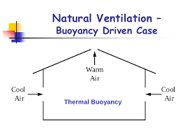
For natural ventilation applications designed to cool indoor spaces, outdoor air serves as the cooling medium. Since outdoor air is typically less dense than indoor air, the proper placement of intake and exhaust louvers is essential to leverage buoyancy effects effectively.
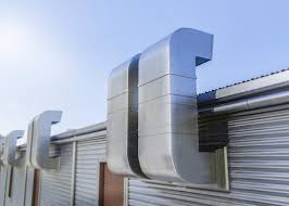
- Intake Louvers: These should be positioned at a low level on the room wall to allow denser, cooler outdoor air to flow into space.
- Exhaust Louvers: Hot air, being less dense, naturally rises. To facilitate its removal, the exhaust louvers should be placed at a high level on the opposite or same wall.
For rooms with multiple outdoor walls, prevailing wind direction of the project location shall be taken into account while selecting the wall for placing the intake louvers.
2.4 Security Considerations
In secure or sensitive areas, locate the intake and exhaust vents in such a way that they do not pose a security risk, making them difficult for intruders to access or exploit.
2.5 Aesthetic and Architectural Considerations
Confirm the proposed locations with the architect, as certain positions may not be acceptable due to aesthetic or design concerns.
2.6 Wind Effect
Consider the prevailing wind direction and ensure the intake is positioned to minimize the impact of strong wind currents, which could affect system performance.
2.7 Raising the Inlet Location
If there is a risk of sand, debris, or pollutants entering from the ground, raise the inlet to an appropriate height to avoid contamination.
2.8 Avoid Pedestrian Areas
Avoid placing intakes or exhausts near pedestrian pathways, especially if high air velocity is anticipated. Such locations can create safety hazards or cause discomfort to people nearby. Additionally, avoid placing intakes near the ground to prevent vandalism.
2.9 Ductwork Design
Intake ductwork may require space for components such as flow sensors, fire/gas dampers, isolation dampers, smoke detectors, and silencers. To accommodate these elements and to provide sufficient straight length and retention time, the intake duct may need to be longer, which will influence the intake location.
2.10 Exhaust Discharge
Ensure that exhausts, including hot air, fumes, smoke, combustion gases, or pollutants, are discharged away from habitable spaces.
Typically, this requires exhaust outlets to be positioned above the roof and distant from the fresh air intake to prevent contamination of the incoming air.
The discharge point of hazardous gas exhaust systems, such as those from battery rooms, is typically classified as a hazardous-rated zone within a specific radius (commonly 2 to 3 meters, called vapour cloud volume). Any E&I equipment or items (light fitting, instruments etc.) placed within this designated zone must be appropriately rated and selected for hazardous area applications to ensure safety and compliance with regulations.
If it is not feasible to use hazardous-rated equipment within this radius, mitigation measures must be implemented. This involves relocating the exhaust discharge point to a location farther away from nearby equipment or items, ensuring an adequate separation distance. This separation prevents any E&I components from being situated within the vapor cloud volume, thereby maintaining safety and operational integrity.
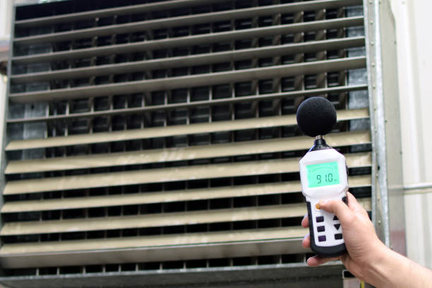
2.11 Noise Considerations
Place both intake and exhaust vents away from external noisy equipment or areas. This helps reduce the potential for noise pollution and maintains a quiet environment inside the building.
3. Conclusion
Proper placement of fresh air intake and exhaust is a critical aspect of HVAC system design.
By following best practices, including maintaining appropriate separation distances, accounting for wind effects, ensuring secure and aesthetically acceptable locations, and preventing airflow short-circuiting, the system can operate efficiently and safely.
Adhering to standards such as ASHRAE 62.1 and incorporating techniques like Computational Fluid Dynamics (CFD) analysis, when necessary, ensures compliance with regulations and optimizes performance.
Additionally, considering factors such as noise, contamination risks, and architectural design further enhances system reliability and occupant comfort.
Ultimately, thoughtful planning and execution of fresh air intake and exhaust locations contribute to improved indoor air quality, effective ventilation, and overall energy efficiency of the HVAC system.
4. References
- ASHRAE Handbook—Fundamentals
- ASHRAE Handbook—HVAC Systems and Equipment
- ASHRAE 62.1 Ventilation and Acceptable Indoor Air Quality
- NFPA 45 Standard on Fire Protection for Laboratories Using Chemicals
5. Abbreviations
| ASHRAE | American Society of Heating, Refrigerating, and Air-Conditioning Engineers |
| CFD | Computational Fluid Dynamics |
| HVAC | Heating, Ventilation, and Air Conditioning |
| IAQ | Indoor Air Quality |
| IC | Internal Combustion |
| NFPA | National Fire Protection Association |
| VOC | Volatile Organic Compounds |