1. Introduction
In this article, we will learn the concept of the critical radius of insulation, and how to select the insulation thickness for a chilled water pipework system.
In HVAC cooling applications, a chilled water-cooled system is normally used for large-scale buildings where the total cooling load is substantial, the number of terminal units is extensive, and the distance between the outdoor unit and indoor air terminal units is significant.
Due to their efficiency and scalability, chilled water systems are well-suited for high-capacity cooling requirements in residential, commercial, industrial, and institutional facilities.
The major components of the CHW systems are terminal units (FCU, AHUs, FAHUs), chillers, chilled water pumps, and a CHW piping system.
2. Chilled Water Piping System
The chilled water piping system includes piping, fittings, inline components such as valves, strainers, air vents, air separators, pressurization unit, chemical injection package, and balancing devices to regulate flow and maintain system efficiency.
This CHW piping system transports chilled water cooling medium between the chiller plant and terminal units.
3. Chilled Water Piping Insulation
Insulation to chilled water (CHW) pipes is a key strategy for minimizing heat transfer (Q) from the surrounding environment to the chilled water.
Insulation on flat surfaces like rectangular ducts or structural walls/walls consistently reduces heat transfer, however, it is always true for curved surfaces. The dynamics of curved surfaces heat transfer, such as CHW pipes, involve more complexity. A concept called the Critical Radius of Insulation (Rcr) governs how insulation behaves on these curved surfaces.
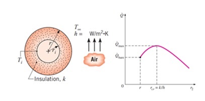
4. Critical Radius of Insulation
When insulation is added to CHW pipes, the heat transfer rate initially increases until the pipe’s radius, including insulation, reaches the critical radius (Rcr). Beyond this point, the heat transfer rate begins to decrease.
This phenomenon occurs due to the interplay between conductive resistance (ln(r/ri)/ (2 x π x L x kins)) and convective resistance (1/2 x π x r x L x h), where:
- r is the outer radius of the insulation.
- ri is the outer radius of the bare pipe.
- kins is the thermal conductivity of the insulation material.
- h is the convective heat transfer coefficient.
- L is the length of the pipe.
For a fixed pipe size, the thermal conductivity of the insulation (kins) and the convective heat transfer coefficient (h) are assumed constant, meaning the radius (r) changes as insulation thickness increases. The critical radius is defined as:
Rcr = kins/h (Refer to “Textbook: Thermodynamics, Yunus A. Cengel and Michale A. Boles”, for the derivations and assumptions)
At the critical radius, conductive and convective resistances are equal. Beyond Rcr, the increasing conductive resistance outweighs the decreasing convective resistance, resulting in a reduction in heat transfer rate (Q).
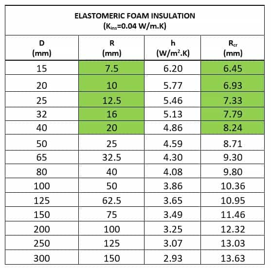
5. Case Study 1: Elastomeric Foam Insulation (kins = 0.04 W/m.K)
Elastomeric foam is a commonly used material for insulating CHW pipes due to its low thermal conductivity (kins = 0.04 W/m.K). For this analysis, we focus on CHW piping routed indoors, typically above false ceilings, where natural convection applies.
The convective heat transfer coefficient for natural convection over a cylindrical surface is given by:
h = 1.04 x (ΔT/D)0.25 (Ref: ASHRAE Handbooks – Fundamentals, Chapter – Heat transfer)
Where:
ΔT = 19°C (CHW temperature = 6°C, ambient temperature = 25°C)
D is the outer diameter of the pipe
The critical radius of insulation is given by:
Rcr = kins/h
Where,
Kins = Thermal conductivity of insulation material, in W/m.K
Below table presents the convective heat transfer coefficient (h) and critical radius (Rcr) calculations for pipe diameters ranging from 15 mm to 300 mm.
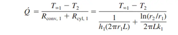
Use the following equation to calculate the heat transfer rate:
From the above tables we can derive the following key points:
- For all pipe diameters, the critical radius (Rcr) is smaller than the outer radius of the bare pipe (r > Rcr).
- As a result, adding insulation always reduces the heat transfer rate, as the system remains beyond the critical radius threshold.
This conclusion is reinforced by the graph below, which plot insulation thickness against the heat transfer rate for a DN15 pipe.
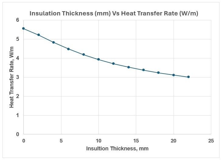
The analysis demonstrates that increasing insulation thickness continuously decreases the heat transfer rate for elastomeric foam insulation.
6. Case Study 2: Arbitrary Insulation Material (kins = 0.1 W/m.K)
In this scenario, a hypothetical insulation material with a higher thermal conductivity (kins = 0.1 W/m.K) is analyzed.
The same methodology of case study 1 is applied to calculate the convective heat transfer coefficient (h) and critical radius (Rcr) for various pipe diameters, as shown in the below table.
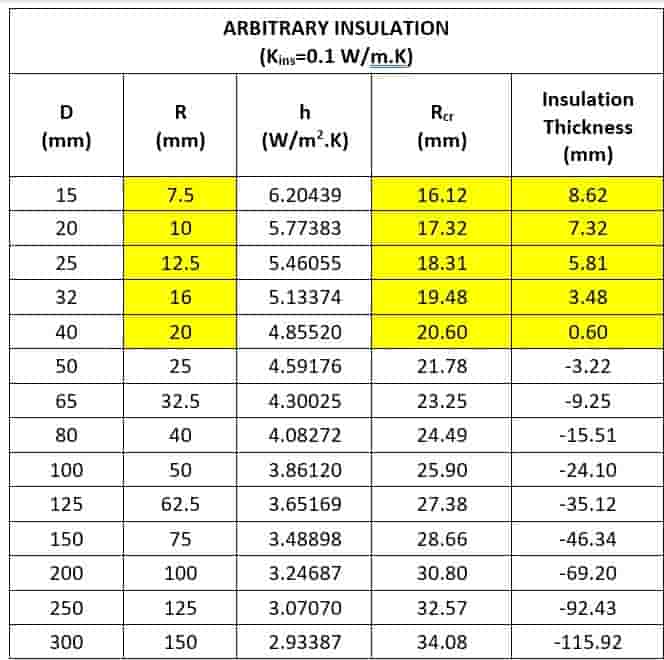
From the above tables we can derive the following key points:
- For smaller-diameter pipes, the critical radius (Rcr) is greater than the outer radius of the bare pipe (r < Rcr).
- In such cases, adding insulation increases the heat transfer rate until the critical radius is reached. Beyond Rcr, the heat transfer rate starts to decrease as the conductive resistance dominates.
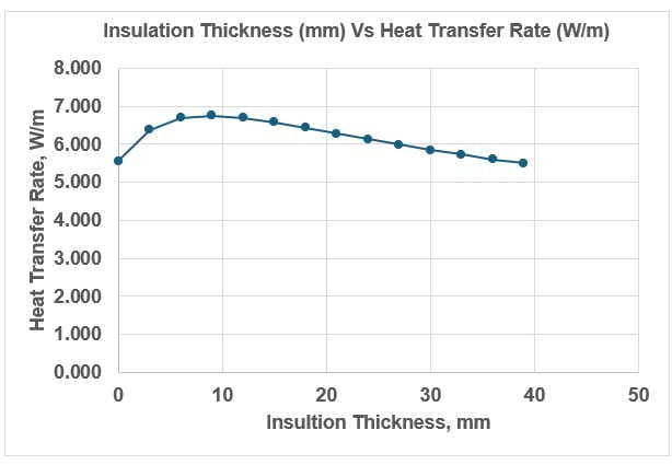
Below table and graph below illustrate the relationship between insulation thickness and heat transfer rate for a DN15 pipe. These results confirm that, for smaller pipes using higher-k insulation materials, the critical radius effect is significant and must be considered to avoid counterproductive outcomes.
7. Discussion
The critical radius of insulation highlights a key difference between flat and curved surfaces in thermal systems. While flat surfaces benefit unconditionally from increased insulation thickness, curved surfaces like pipes exhibit a more complex relationship. The interplay between conductive and convective resistances determines whether additional insulation will increase or decrease the heat transfer rate. This effect is influenced by:
- Thermal Conductivity of Insulation (kins):
- Lower thermal conductivity materials (e.g., elastomeric foam) result in smaller critical radii, ensuring that most practical pipe sizes are beyond the critical radius, leading to a consistent reduction in heat transfer rate.
- Pipe Diameter:
- Smaller-diameter pipes are more susceptible to the critical radius effect, especially when using higher-k insulation materials.
- Convective Heat Transfer Coefficient (h):
- The value of h depends on the temperature difference (ΔT) and pipe diameter (D). For natural convection, h decreases with larger diameters, which can influence the critical radius calculation.
8. Conclusion
When selecting insulation for curved surfaces such as chilled water pipes, it is essential to account for the critical radius of insulation. The choice of insulation material, its thickness, and thermal conductivity (k) must be carefully evaluated to ensure optimal thermal performance. Neglecting the critical radius effect can lead to unintended consequences, particularly for smaller-diameter pipes or higher-k materials, where improper insulation could increase heat transfer instead of reducing it.
For most indoor applications using elastomeric foam insulation (kins = 0.04 W/m.K), the critical radius effect is negligible, and adding insulation reliably reduces the heat transfer rate. However, for alternative materials or smaller pipes, engineers must perform detailed calculations to determine the critical radius and ensure efficient insulation design.
9. References
- ASHRAE Handbook – Fundamental, Chapter “Heat Transfer”
- Textbook: Thermodynamics, Yunus A. Cengel and Michale A. Boles
10. Abbreviations
| AHU | Air Handling Unit |
| ASHRAE | American Society of Heating, Refrigerating, and Air-Conditioning Engineers |
| CHW | Chilled Water |
| FAHU | Fresh Air Handling Unit |
| FCU | Fan Coil Unit |
| HVAC | Heating, Ventilation, and Air Conditioning |