The main purpose of this blog is to explain the importance of correctly locating the temperature sensor/thermostat inside the conditioned room, for a comfort air conditioning application.
1. What is Comfort Air-Conditioning?
Comfort air conditioning refers to an HVAC system that controls and maintains the enclosed indoor room air parameters such as dry bulb temperature, airflow residual velocity, and humidity value within the specified design ranges.

These parameters of the room air must be carefully controlled and maintained to ensure that the human occupants feel thermally comfortable (i.e., that condition of mind expresses satisfaction with the surrounding thermal environment, in this case with room air).
The recommended comfort conditions such as dry bulb temperature, RH, and residual velocity conditions of room air are given in the below table:
| Sl. No | Room air parameters | Summer design range | Winter design range | Remarks |
| 1 | Dry bulb temperature | 22 to 26°C (72 to 78°F) | 20 to 24°C (68 to 75°F) | |
| 2 | Relative humidity | 40 to 60% | 30 to 50% | |
| 3 | Residual velocity | 0.15 to 0.25* m/s (30 to 50* FPM) | Slightly lower value than the cooling | |
| *Higher residual air velocity can cause thermal discomfort, reduced productivity, and health issues due to the cold draft effect. | ||||
2. Parameters that Affect Thermal Comfort
Parameters that affect human thermal comfort are divided into two major categories, such as primary and secondary.
2.1 Primary Factors
The primary parameters that directly affect the energy flow between the human body and surrounding air and consequently the human thermal comfort.
Refer to the below list for the primary 6 factors.
- Metabolic rate
- Clothing insulation
- Air temperature
- Radiant temperature
- Airspeed
- Humidity
2.2 Secondary Factors
Below are the secondary parameters that subtly influence thermal comfort.
- Age
- Sex
- Seasonal and Circadian Rhythms
- Adaptation
- Day-to-Day Variations
Note that the main purpose of this blog is to explain the importance of temperature sensor location in thermal comfort applications. To better understand how the above primary and secondary parameters affect human thermal comfort, the reader should refer to the “ASHRAE 55” standard.
3. HVAC System and its Components

An HVAC system is essential to control and maintain the room air temperature, humidity within the desired design limits. The HVAC system typically includes various components such as Chillers, Package A/C units, FAHUs, AHUs, FCUs, Humidifiers, pumps, ventilation fans, ductwork, and piping (in the case of central systems), an electrical power distribution system, a control system, and temperature sensors. These components work together to regulate the indoor environment and ensure consistent thermal comfort.
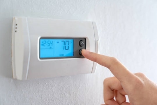
4. Temperature Control
Room air temperature is controlled by continuously sensing the actual room air temperature and comparing it with the desired design setpoint temperature value.
When the actual air temperature exceeds the set point value, the HVAC system’s cooling equipment is activated by the control system to bring the temperature back within the desired range. Conversely, when the actual room air temperature falls below the set point, the system will trigger the heating equipment to restore the comfort levels.
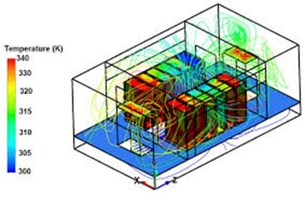
5. Temperature Variation Within the Conditioned Room
Within an air-conditioned space, both the room air temperature and the surface temperature of the enclosed walls can vary across different points in the room and wall respectively. These temperature variations occur due to the following major factors:
5.1 Supply Air Temperature
In the cooling mode of human comfort applications, the supply air temperature is normally about 10°C lower than the room air design temperature (usually 24°C).
The mixing between these colder supply air and the room air results in temperature variations at different points within the room/space.
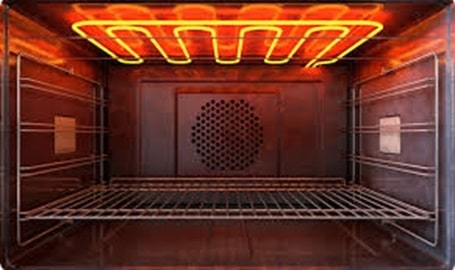
5.2 Heat Emitting Equipment/Items
Appliances such as ovens, burners, photocopiers, refrigerators, table lamps, radiators, etc., emit heat during their operation, and this will cause localized temperature raise.
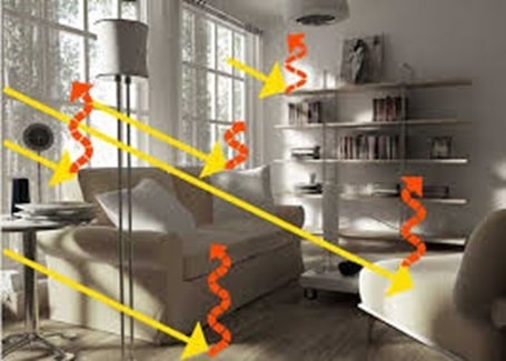
5.3 Solar Radiation
The solar radiation energy that passes through the glazed windows located on the exterior walls, when intercepted by the room object/floor/wall, will lead to localized heating and consequent increases in the local temperature.
5.4 Heat Transfer through Exterior Walls
During extreme summer conditions, the external surface temperature of exterior walls will be much higher than the outdoor air temperature.
The external surface temperature can be approximately equal to the sol-air temperature (which is a function of irradiation, emittance, absorptance of surface, and convective heat transfer coefficient) specified in the table below. Note that at certain times of the day, the external surface temperature is about 32 OC higher than the outdoor air temperature for a given wall structure.
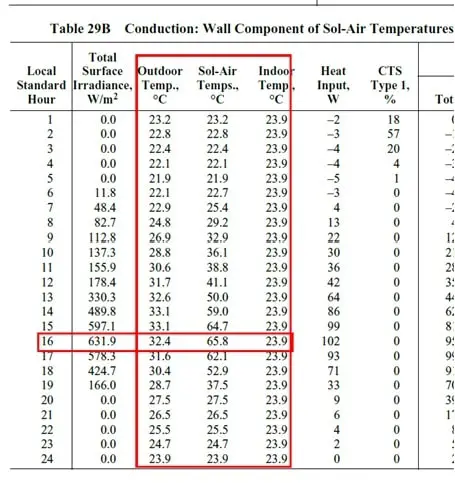
So, the heat energy transfer occurs from the external surface towards the internal surface and if the temperature sensor/thermostat is located on the interior side of the external wall (refer to below image), then it will affect the temperature reading as well as lead to improper operation of the HVAC system.
5.5 Frequent Door Openings
Some rooms (like the building entrance lobby, and commercial outlets on the ground floor) will have door (s) which may open to outdoor ambient air and due to human traffic these doors have to be opened frequently.

Frequent opening of doors will introduce hot outdoor air into the space, further contributing to temperature variation inside the room.
6. Importance of Temperature Sensor Location
As I explained in the previous section, room air temperature variations exist within a conditioned room. Therefore, placing temperature sensors within the room in a correct location that represents the whole room temperature is critical for maintaining accurate system control and ensuring optimal performance. These sensors must be strategically placed at representative points within the room to ensure accurate readings of the room’s overall temperature.
The rightly placed temperature sensors provide the following major advantages:
6.1 Achieve Effective System Control
Accurate temperature readings enable the HVAC system to maintain consistent thermal comfort conditions.
6.2 Optimize Energy Efficiency
Correct sensor placement can prevent the HVAC system from running longer than necessary, reducing electrical energy consumption and associated reduction in operating costs.
6.3 Sustainable Design
An optimally placed temperature sensor reduces the HVAC system’s electrical power consumption (Refer to above).
In regions where electrical power is generated and distributed by burning fossil fuels (including coal, oil, and natural gas), the following advantages will be obtained:
- Reduced air pollution (Such as SO2, nitrogen oxides (Nox), and particulate matter) release into the atmosphere and associated reduction in human health issues.
- Reduction in green gas emission (mainly CO2) ito the ambient air and associated reduction in global warming effect.
6.4 Increase in HVAC System Plant Life
As the overrunning of the HVAC system is avoided, the wear and tear of the system moving component is reduced and thus life of the HVAC system plant is increased.
6.5 Avoid Operational Issues
Improper sensor placement may lead to incorrect readings, triggering unnecessary system adjustments or malfunctions. Rightly placed sensors will avoid these issues.
7. Ideal Location for Room Temperature Sensor
To ensure accurate and reliable temperature measurements, the following guidelines should be followed when designing and installing the room temperature sensors:
7.1 Installation Height
Install the temperature sensor approximately 1.5 meters (5 feet) above the finished floor level, ensuring it accurately reflects the room’s air temperature at occupant head level.
Based on the application this height will vary between 1.1 m to 1.7 m.
7.2 Internal Walls
Place sensors on internal walls, ideally those separating adjacent rooms with similar design temperatures. This will ensure that the sensor measures representative conditions in the room.
7.3 Proximity to Return Air
Position the sensor closer to the return air path, while keeping it away from the supply air, and vent to avoid skewed readings caused by direct airflow.
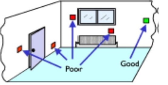
7.4 Avoid External Walls
Refrain from placing sensors on external walls, as these are subject to temperature fluctuations due to external environmental conditions. If sensor placement on external walls is unavoidable, insulating materials should be used between the sensor and the wall.
7.5 Avoid Heat Sources
Ensure that sensors are located away from internal heat sources such as ovens, photocopiers, refrigerators, table lamps, radiators, and other appliances that could affect the readings.
7.6 Distance from Corners and Vertical Obstacles
Install sensors at least 0.5 meters (1.5 feet) away from corners or vertical obstructions to avoid areas with stagnant air, where temperature may not be representative of the overall room environment.
7.7 Avoid Direct Sunlight
Place sensors away from direct sunlight that passes through the windows located on the external wall. Direct sunlight on to the temperature sensor will lead to an artificial raise in temperature reading and it will not reflect the actual room temperature reading.
7.8 Minimize Proximity to External Doors
Sensors should not be placed near doors that open frequently to the outside, as this can introduce untreated outdoor air and affect the temperature readings.
7.9 Avoid Obstructions
Ensure that the temperature sensors are located such that the airflow movement to the sensor is not blocked by the curtains, room furniture, or other objects that could impede airflow and interfere with accurate temperature measurement.
7.10 Don’t Install Inside the Isolated Box
Temperature sensors should be installed in a location with proper room air circulation and must not be isolated from the ambient air of the room.
In one of the projects, I encountered an issue where the temperature sensor was installed inside a locked cabinet that houses heat-emitting electrical items. Upon further investigation, I discovered that the concerned conditioned space was a high human traffic common area. To prevent potential damage to the sensor or unauthorized adjustments by passersby, the sensor has been placed inside the locked cabinet. However, this setup led to inaccurate temperature readings, as the sensor was influenced by the heat generated within the cabinet rather than reflecting the actual room conditions.
This example highlights the importance of thoughtful sensor placement. While protecting the sensor from physical damage and tampering is valid, it should not compromise its ability to measure the room’s temperature accurately. Alternative solutions, such as protective covers or strategically placed, tamper-resistant enclosures that still allow for proper air circulation, can address both concerns effectively.
8. References
- BSRIA Guide – Design Checks for HVAC
- ASHRA Handbook – Fundamental
- ASHRAE 55 – Thermal Environmental Conditions for Human Occupancy
9. Abbreviations
| AHU | Air Handling Unit |
| ASHRAE | American Society of Heating, Refrigerating, and Air-Conditioning Engineers |
| BSRIA | Building Services Research and Information Association |
| FAHU | Fresh Air Handling Unit |
| FCU | Fan Coil Unit |
| FPM | Feet per Minute |
| HVAC | Heating, Ventilation and Air Conditioning |
| RH | Relative Humidity |