1. Introduction
In HVAC systems, insulation is applied on the surfaces of the wall, roof, ductwork, pipework, and equipment for the following reasons:
- Cold conservation (by thermal insulation)
- Heat conservation (by thermal insulation)
- To avoid surface condensation
- To achieve the required fire rating of the wall, deck, and ductwork
- To minimize sound/noise propagation
- Personnel protection from high surface temperature
In this article, we will learn how to calculate and select the thermal insulation thickness for cold conservation which will optimize the HVAC system’s energy efficiency, Initial cost, space, and weight.
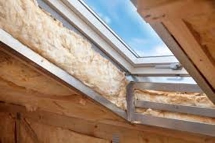
For analysis purposes, the wall insulation of the steel building has been considered. However, a similar analysis can be done for the HVAC pipe works, ductwork, and equipment.
2. Governing Equation for Heat Transfer Rate (Q)
Consider an air-conditioned enclosure/room made of steel walls on all sides.
The following assumptions are made:
- Heat transfer is one-dimensional and it flows perpendicular to the external wall surface
- The heat transfer is instantaneous (i.e., the storage effect of the wall is ignored)
- The heat transfer rate is steady
- There is no glass window/door on the external wall
- Analysis will be limited to only the walls. The roof and floor are ignored
- Thermal conductivity value is assumed to be constant
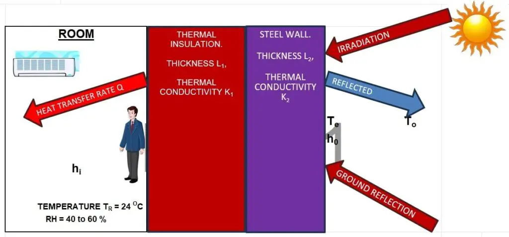
By applying the above assumptions, the combined conduction, convection, and radiation heat transfer governing equations will be deduced as below:
Q = U x A x (Te-TR)
Where,
Q = Heat transfer rate, W
U = Overall heat transfer co-efficient, W/m2.K
A = Surface area of the external wall, m2. (For this analysis consider A = 100 m2)
TR = Room temperature, OC. Consider 24 OC DBT
Te = Sol-air temperature, OC.
3. Sol-air Temperature (Te)
The ASHRAE definition of Sol-air Temperature is given below:
“Sol-air temperature is the outdoor air temperature that, in the absence of all radiation changes gives the same rate of heat entry into the surface as would the combination of incident solar radiation, radiant energy exchange with the sky and other outdoor surroundings, and convective heat exchange with outdoor air”
Note that, for vertical wall surfaces, the “Sol-air temperature” is not the same as the ambient air temperature. For the wall, “Sol-air temperature” is a function of ambient air temperature (T0), total solar radiation incident on the wall surface, (Et), the absorptivity of the external wall surface (α), and the heat transfer coefficient of the outer wall (ho). As all these values (α, Et, ho) are positive values, Sol-air temperature will be higher than the ambient air temperature
Te = To + (α x Et / ho)
Where,
α = 0.50 (For steel wall, assumed colour of sandstone painted, Ref [2])
To = 46 OC (Consider design ambient dry bulb temperature for Dubai, UAE)
h0 = 17 W/m2.K (from Carrier HAP software)
Et = 780 W/m2. (Et varies with time, location, and orientation). Specified value is assumed for this analysis
Apply these values in the above Te equation:
Te = 46 + 0.50×780/17
Te = 46 + 22.94
= 68.9 OC
Note to the reader: Read the “ASHRAE Handbook, Fundamentals, Chapter, Nonresidential Cooling and Heating Load Calculations”, to learn more about the “Sol-air temperature” concept and absorptivity of materials.
4. Overal Heat Transfer Coefficient (U)
U = (1/(1/hi+L1/K1+L2/K2+1/ho))
Where,
hi = Internal surface heat transfer coefficient, W/m2.K. hi = 8.29 W/m2.K, (Ref: [6])
L1 = Thickness of thermal insulation, m. Variable
K1 = Thermal conductivity of thermal insulation, W/m.K. K1 = 0.045 W/m.K (Ref: [8])
L2 = Thickness of thermal steel wall, in meters. L2= 8 mm = 0.008 m
K2 = Thermal conductivity of steel, W/m.K. K2 = 45.3 W/m.K (Ref: [1])
h0 = External surface heat transfer coefficient, W/m2.K. h0=17.05 W/m2.K, (Ref: [6])
As the effect of the last term (1/h0) is already included in the “Sol-air temperature” concept, the U-value will be reduced as below:
U = (1/(1/hi + L1/K1 + L2/K2))
= (1/(1/8.29 + L1/0.045 + 0.008/45.3))
= 1/(0.121+22.22 x L1)
5. Simplified Governing Equation for Heat Transfer Rate (Q)
The simplified heat transfer equation is given below:
Q = U x A x (Te-TR)
= 1/(0.121 + 22.22 x L1) x A x (Te– TR)
Q = 1/(0.121 + 22.22 x L1) x 100 x (68.9- 24)
= 1/(0.121 + 22.22 x L1) x 4490
= 4490/(0.121 + 22.22 x L1)
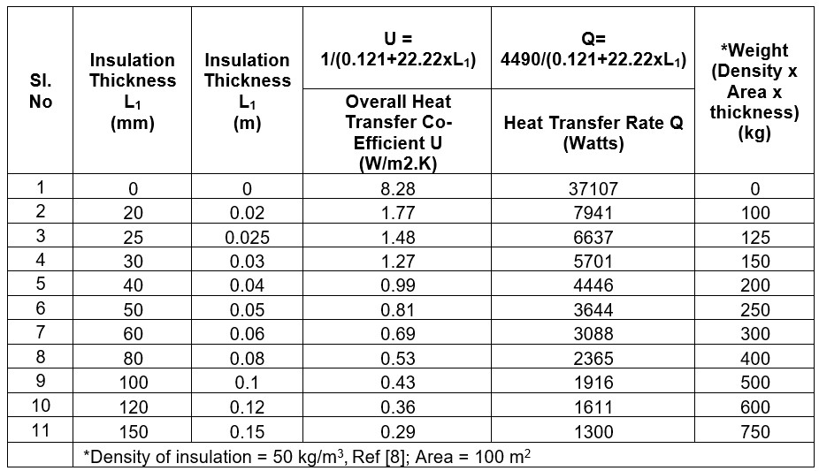
6. U-value, Heat Transfer Rate (Q), and Weight Calculation
Using the above simplified governing equations, the U-value and heat transfer rate (Q) have been calculated for various insulation thicknesses (20, 25, 30, 40, 50, 60, 80, 100, 120, and 150 mm) and are presented in the table below.
The weight of the insulation has also been determined using the formula:
Weight=Density (kg/m³) × Area (m²) × Thickness (m)
For simplicity, the weight of supporting components such as the frame, fasteners, and other items holding the insulation has been excluded from the calculation.
7. Conclusion
Overall Heat Transfer Coefficient (U)
The graph below illustrates the relationship between insulation thickness (L1) and U-value.
As insulation thickness (L1) increases, the overall heat transfer coefficient (U) decreases; however, this reduction is nonlinear.
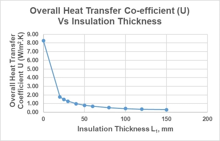
The U-value decreases sharply with the application of the initial 20 mm of insulation. For insulation thicknesses between 25 mm and 50 mm, the reduction becomes more moderate. Beyond 50 mm, further increases in insulation thickness result in only minimal changes to the U-value.
Heat Transfer Rate (Q) and Weight
The graph below illustrates the relationship between insulation thickness (L1) and heat transfer rate (Q).
As insulation thickness (L1) increases, the total heat transfer rate (Q) decreases; however, this reduction is nonlinear.
Observations
- Significant Reduction: The most substantial reduction in the heat transfer rate occurs when the insulation thickness increases from 0 mm to 20 mm, with a 78.6% reduction.
- Moderate Reduction: Between 25 mm and 50 mm of insulation, the reduction in Q becomes more moderate, with percentages ranging from 82.1% to 90.2%.
- Minimal Reduction Beyond 50 mm: Increasing insulation thickness beyond 50 mm yields diminishing returns, as the reduction in the heat transfer rate (Q) becomes progressively smaller. For example, at 150 mm, Q is reduced by 96.5% compared to the uninsulated case. However, the additional 100 mm of insulation thickness (from 50 mm to 150 mm) contributes only a 6.3% further reduction in the heat transfer rate. In contrast, the added insulation weight increases significantly, by 200%, for this additional 100 mm thickness. This highlights the trade-off between thermal performance gains and the associated increase in material weight.
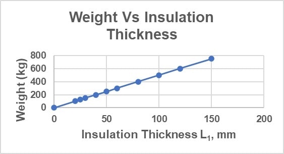
The total weight increases proportionally with the insulation thickness (L1)
This behavior aligns with the principles of heat conduction, where adding insulation reduces heat transfer but does not eliminate it entirely.
The initial addition of insulation has a more pronounced effect, while subsequent increases yield diminishing returns.
Based on a country’s climatic zone classification (Climate Zones 0 to 8, as defined by ASHRAE Standard 169), the acceptable minimum R-value and maximum U-value for various applications—residential, non-residential, or semi-heated—are specified in ASHRAE Standards 90.1 and 90.2. These values apply exclusively to the insulation material itself and do not account for additional resistance factors such as internal/external heat transfer coefficients or other building materials.
In most projects, client or company specifications typically dictate the acceptable maximum U-value.
Therefore, selecting the appropriate insulation thickness requires balancing several factors, including compliance with the project specification/ASHRAE 90.1,90.2, insulation’s initial cost, return on investment, weight, and the space it occupies. This careful consideration ensures compliance with thermal performance requirements while optimizing cost and practicality.
8. References
- ASHRAE Handbook – Fundamental, Chapter “Physical Properties of Materials”
- ASHRAE Handbook, Fundamentals, Chapter, Nonresidential Cooling and Heating Load Calculations
- ASHRAE Standard 169 Climatic Data for Building Design Standards
- ASHRAE Standard 90.1 Standard Energy Standard for Buildings Except Low-Rise Residential Buildings
- ASHRAE Standard 90.2 Standard Energy Standard for Buildings Low-Rise Residential Buildings
- Carrier HAP Software, “Wall”, for Inside and Outside Surface Resistance (Converted to inside and outside convective heat transfer coefficient (h) by taking the reciprocal)
- Textbook: Thermodynamics, Yunus A. Cengel and Michale A. Boles
- Manufacturer (PAROC) Catalogue: 2022_PAROC-Pro-Lamella-Mat-AluCoat-en-US
9. Abbreviations
| DBT | Dry Bulb Temperature |
| HAP | Hourly Analysis Program |
| HVAC | Heating, Ventilation, and Air Conditioning |
| UAE | United Arab Emirates |