1. Purpose
The purpose of this article is to learn the limitations of McQuay Duct Sizer Tool, that everyone uses for sizing the duct.
In this article, we will touch little bit about the duct sizing basis, however the intention of this article is not to teach “how to size the ductwork system” and for the same I will write a separate article later.
2. Ductwork Introduction
In HVAC system, the ductwork serves as a pathway to move the required design airflow between various locations, with the help of fans, as below:
- Distribute the airconditioned air (heated, cooled, or ventilated) throughout a building.
- Extract the clean room air and return back to the equipment (such as AHUs, FAHUs, FCUs etc.)
- Take the outdoor fresh air to the FAHUs, and AHUs
- Extract the fouled, polluted, and hazardous air and discharge into the safe area
- Discharge the excess air resulting from the pressurization to outdoor
3. Ductwork Material of Construction
Based on the application requirement, normally the ductworks are made of the following materials:
- GI (of different zinc coating thickness)
- Stainless steel (of different grades)
- Aluminium
- Carbon steel
- Pre-insulated duct (PID), made of Polyurethane/Phenolic Foam
- Concrete, for staircase and smoke management applications
- Flexible duct (Spiral wore frame with foil or fabric, and insulation)
- Fiberglass ductboard
- Plastic
- Fabric
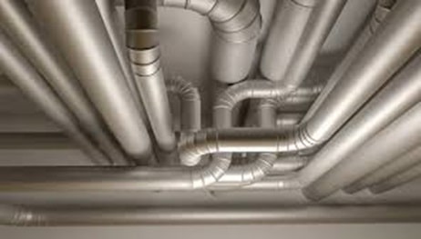
4. Flow Resistance by Ductwork System
When the air is pushed by the fan to move the air through the ductwork system (including duct, air terminals, fittings, and inline items), it offers resistance to the flow.
The flow resistance offered by the straight ductwork is called “Frictional resistance” and the flow resistance offered by the fittings, inline items are called “Dynamic resistance”. Note that the energy required to overcome these resistances are irreversible and it get converted into heat, so these lost energies are called Frictional losses and Dynamic losses, respectively.
Frictional Flow Resistance
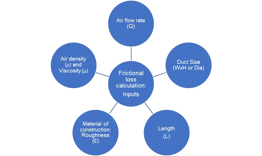
The frictional flow resistance (Pa) is the function of below parameters:
- Size and shape of the duct
- Length of the ductwork
- Airflow rate
- Material of construction (Mainly the roughness Ɛ)
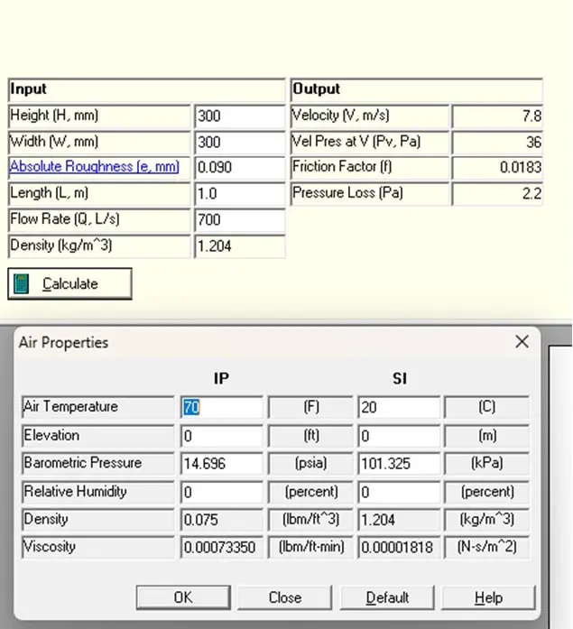
- Density (ρ) and viscosity (µ). To fix a state point of moist air in psychrometric and to read the density/specific volume, three parameters (1) Atmospheric pressure 2) any other two parameters DBT & WBT or DBT & RH or WBT & RH) should be known. The ASHRAE DFDB allows to enter DBT & RH. Instead of pressure, altitude of site location can also be entered.
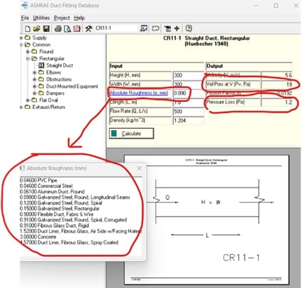
Refer below the extract from the “ASHRAE Duct Fitting Data Base”, software. All the white box values (mentioned above) are input values and should be filled in by the designer as a input. The software will give the frictional loss value (Pa).
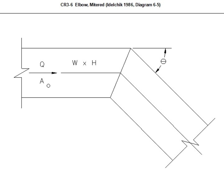
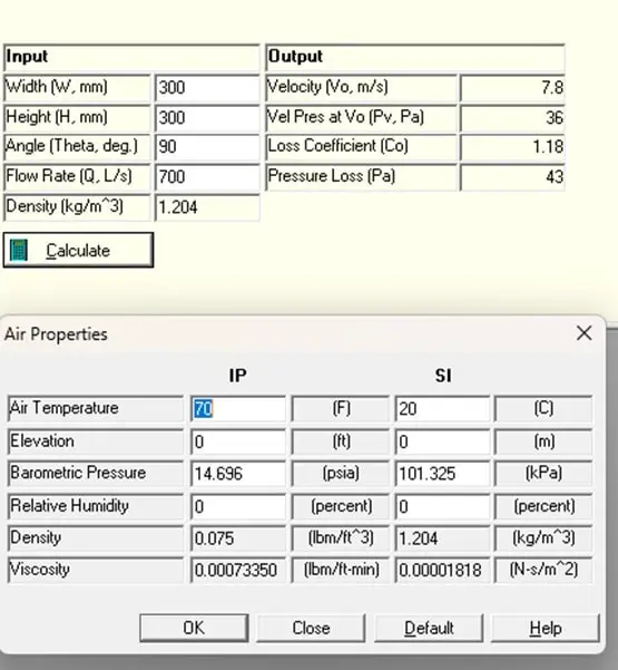
Dynamic Flow Resitance
The dynamic loss (resistance) is a function of size, shape, airflow rate, density and geometry of the fitting (attributing by the dynamic loss co-efficient). Note that, roughness factor and length parameter inputs are not applicable to dynamic loss.
5. Importance of Proper Duct Sizing
To achieve the design air flow rate, the fan and its motor must be selected to overcome the airflow resistance offered by the ductwork system. Typically, the electrical energy consumed by the fan and motor is approximately 20 to 40% of the overall HVAC system energy consumption.
This electrical energy consumption can be significantly reduced through proper duct sizing. Correctly sized ductwork minimizes pressure losses and ensures efficient airflow, reducing the workload on the fan and motor. Incorrectly sized ductwork will not deliver the design airflow rate.
Therefore proper duct sizing is crucial for delivering the required design airflow rate and also for optimizing the electrical energy, and thus lowering the operational cost of HVAC system.
6. Duct sizing software/tools
For HVAC duct sizing, various software, graphs, tools are commonly used, including:
- ASHRAE DFDS
- Friction charts
- McQUAY duct sizer software
- SMACNA duct design calculator
- ACCA DuctWheel
- or other similar tools.
The choice of tool depends on the specific needs of the application.
7. Duct sizing basic
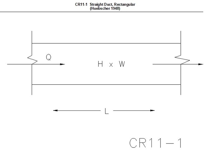
The following equations are the basis for calculating the frictional loss (or head loss) in the straight duct.
Darcy- Weisbeck equation
The frictional loss hf = fxLxV2/2gD.
Where,
hf = Frictional head loss (meter of fluid)
f = Friction factor (dimensionless)
L = Duct length (meters)
D = Hydraulic diameter of the duct (meters) , 4A/P (A= Flow area, m2, P = Perimeter, m)
V = Average air velocity (m/s)
g = Gravitational acceleration (9.81 m/s2)
Colebrook-white equation
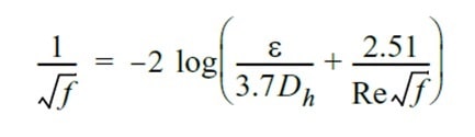
where
Ɛ = material absolute roughness factor, mm
Re = Reynolds number
Reynolds number
Re = VxDh/ʋ
Where,
ʋ = Kinematic viscosity (m2/s)
8. Case Study
Different duct materials are used depending on the application (Refer to section 3 of this article).
The duct material of construction affects the required duct size for a given airflow rate (Q) and design average air velocity (V). In fact, for the same size, different materials can result in varying levels of flow resistance, which, in turn, affects the average air velocity and the resultant pressure loss as well. This difference is primarily due to the surface roughness (Ɛ) of the materials, which varies between them.
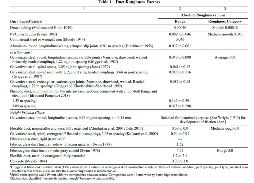
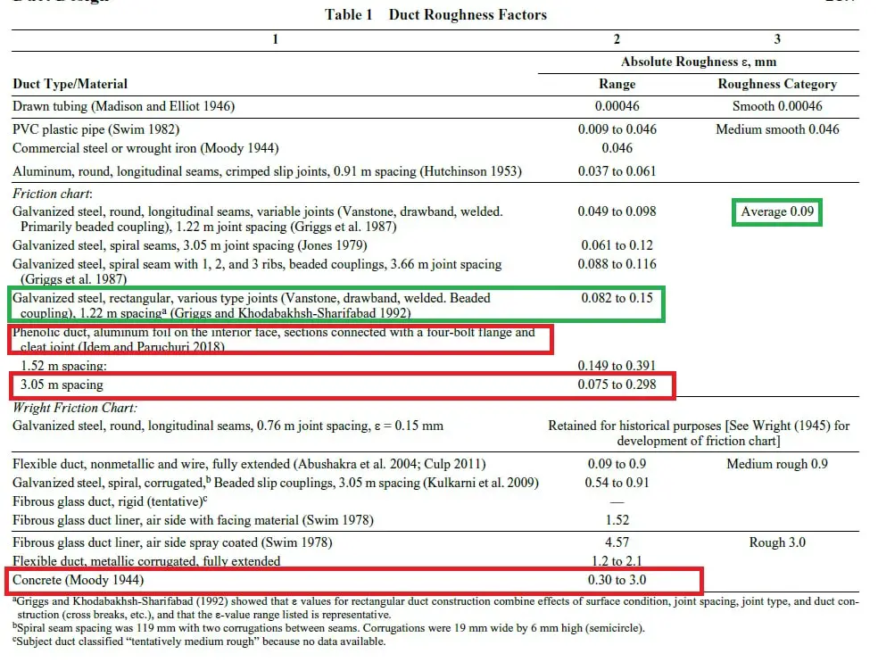
Referencing the attached table, sourced from ASHRAE Fundamentals, Chapter on Duct Design, provides the surface roughness values for different materials.
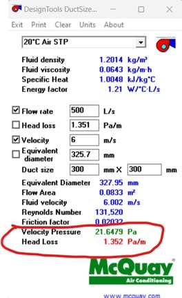
To illustrate the impact of surface roughness factor, let us consider a straight duct with a design flow rate of 500 L/s and a size of 300 mm x 300 mm.
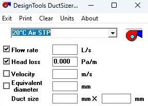
McQUAY
The McQUAY software, does not allow for customization of the surface roughness value (Ɛ). Therefore, the pressure drop (Pa/m) calculated by McQUAY software is based on its default standard settings, which is not known.
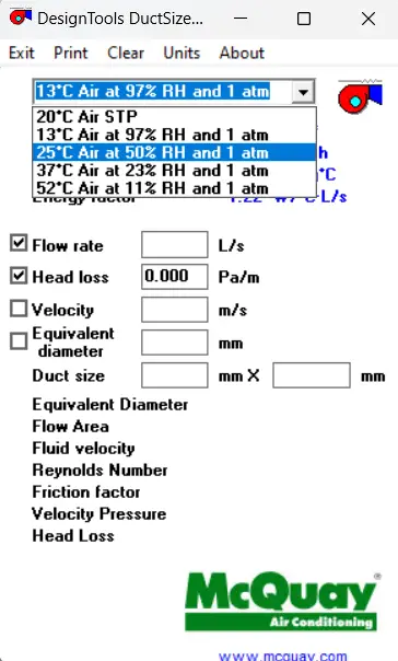
Also in McQUAY, only five temperature values (13 , 20, 25, 37, 52 OC) at standard atmospheric pressure, 1atm, can be chosen. Based on the selected temperature, density and viscosity of the air is taken for frictional pressure loss. Note that, the actual project location (as altitude changes from sea level) will have different atmospheric pressure and this affects the density of air. This is one of the drawbacks of McQuay
ASHRAE DFDB
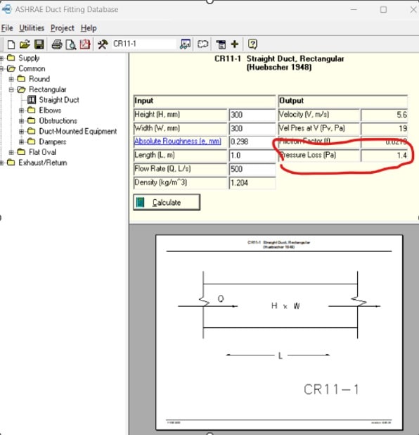
On the other hand, the ASHRAE Duct Fitting Database (DFDB) Software allows users to input specific surface roughness values (Ɛ) as well as inputs required for density (i.e, atmospheric pressure and RH).
By utilizing this software, the pressure drop (Pa/m) for various materials, including standard GI, aluminum (phenolic), and concrete have been calculated.
McQUAY DUCT SIZER
ASHRAE – Ɛ=0.09 (GI DUCT)
ASHRAE – Ɛ=0.298 (PHENOLIC DUCT)
ASHRAE – Ɛ=3 (CONCRETE SHAFT)

The calculated pressure drop values are summarized below:
- McQuay (Standard Ɛ, unknown value) = 1.352 Pa/m
- ASHRAE (Ɛ=0.09, GI) = 1.2 Pa/m
- ASHRAE (Ɛ=0.298, Pre-insulated Aluminium duct) = 1.4 Pa/m
- ASHRAE (Ɛ=3, Concrete, shaft) = 2.4 Pa/m
From the above results we can understand the fact that, for a given design airflow rate (Q) and for the selected same duct size (W x H), the Concrete shaft offers about 100% more resistance than the standard GI ductwork.
This additional resistance will affect the fan ESP, and fan power.
9. Conclusion
The user of “McQuay Duct Sizer” Tool should be aware of the surface roughness effect (Ɛ, i.e., material selection) on duct sizing and should use the right tool for duct sizing; otherwise, the selected fan will not deliver the required design airflow rate and subsequently the design conditions (Such as, room/space temperature, pressure, RH, residual velocity) cannot be met.
10. References
- ASHRAE Handbook – Fundamental, Chapter “Duct Design”
- “ASHRAE Duct Fitting Data Base” software
- “McQUAY Duct Sizer” software
11. Abbreviations
| AHU | Air Handling Unit |
| ASHRAE | American Society of Heating, Refrigerating and Air-Conditioning Engineers |
| DBT | Dry Bulb Temperature |
| DFDS | Duct Fitting Database Software |
| FAHU | Fresh Air Handling Unit |
| FCU | Fan Coil Unit |
| HVAC | Heating, Ventilation, and Air Conditioning |
| PID | Pre-Insulated Ductwork |
| RH | Relative Humidity |
| WBT | Wet Bulb Temperature |