1. Introduction
In HVAC systems, insulation is applied on the surfaces of the wall, roof, ductwork, pipework, and equipment for the following reasons:
- Cold conservation (by thermal insulation)
- Heat conservation (by thermal insulation)
- To avoid surface condensation
- To achieve the required fire rating of the wall, deck, and ductwork
- To minimize sound/noise propagation
- Personnel protection from high surface temperature
In many applications, achieving the desired thermal resistance, fire safety, noise control, or a combination of these requires using multi-layer insulation with varying materials and thicknesses.
This article explores how the sequence of insulation materials with different thermal conductivities influences overall thermal resistance and heat transfer rates in two specific applications: flat surfaces (walls) and curved surfaces (such as piping)
Consider two layers of thermal insulation of different materials as below:
- Thickness of each insulation material L1, L2 = 50 mm (= 0.05 m)
- Thermal conductivity of insulation material-1 k1 = 0.05 W/m. K
- Thermal conductivity of insulation material-2 k2 = 0.1 W/m. K
2. Flat Wall Application
Case-1
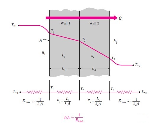
Consider an air-conditioned enclosure/room made of steel walls and two layers of thermal insulations (having thickness and thermal conductivities as specified in Section 1).
Governing Equation for Heat Transfer Rate (Q)
Refer to the below picture for the arrangement.
The following assumptions are made:
- Heat transfer is one-dimensional and it flows perpendicular to the wall surface
- Thickness of steel wall material is negligible ( t ≈ 0) and resistance offered by the steel wall material is zero.
- The heat transfer is instantaneous (i.e., the storage effect of the wall is ignored)
- The heat transfer rate is steady
- Thermal conductivity value is assumed to be constant
- There is no contact resistance between two layers of insulation
By applying the above assumptions, the combined conduction, convection heat transfer governing equations will be deduced as below:
Q = U x A x (T∞1-T∞2)
U= (1/(1/h1+L1/k1+L2/k2+1/h2))
Where,
Q = Heat transfer rate, Watts
U = Overall heat transfer co-efficient, W/m2.K (= 1/R, R = Total Thermal resistance, m2.K/W)
A = Surface area of the external wall, m2. (For this analysis consider A = 1 m2)
T∞1 = Un-conditioned space temperature, OC. Consider 35 OC DBT
T∞2 = Room temperature, OC. Consider 25 OC DBT
h1, h2 = 8.3 W/m2.K (Taken from Carrier HAP software, Wall input, reciprocal of inside surface resistance 0.12064 m2.K/W
Overall heat transfer co-efficient U = (1 / (1/8.3 + 0.05/0.05 + 0.05/0.1 + 1/8.3))
= (1/(0.121 + 1 + 0.5 + 0.121))
= 0.574 W/m2.K
Heat transfer Rate Q = U x A x (T∞1-T∞2)
= 0.574 x 1 x (35 – 25)
= 5.74 Watts.
Case-2
Now just interchange the sequence of insulation, as shown below, and keep the rest of the properties (temperature, insulation thickness, etc.) the same.
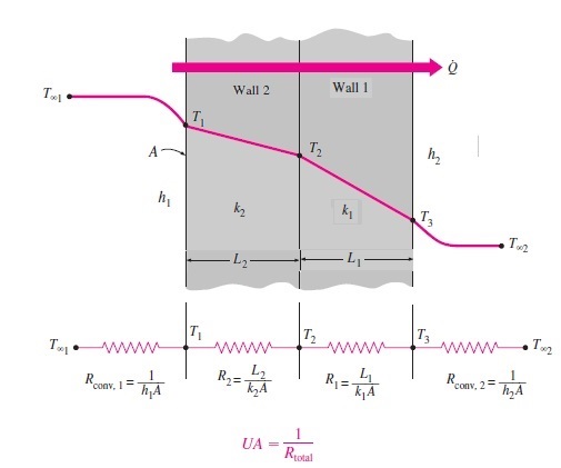
Overall heat transfer co-efficient U = (1/(1/h1+L2/k2+L1/k1+1/h2))
= (1/(0.121 + 0.51 + 1 + 0.121))
= 0.574 W/m2.K
Heat transfer rate Q = U x A x (T∞1-T∞2)
= 0.574 x 1 x 10
Q = 5.74 Watts.
Conclusion
In flat wall applications, interchanging/swapping the insulation sequence does not affect the total thermal resistance (R), overall heat transfer co-efficient (U), and heat transfer rate (Q).
In the next section we will understand the sequencing effect on the curved surfaces (i.e., on the pipework application).
3. Cylindrical Surface
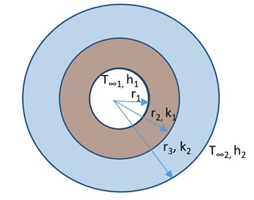
Case-1
Consider the following piping arrangement. Hot water is flowing through the pipe. For this analysis, we will take the same insulation materials, and thicknesses which we have used in the wall application example (in above section 2).
Assume the following details:
Inside fluid temperature T∞1 = 35 OC
Outside fluid temperature T∞2 = 25 OC
Inside convective heat transfer co-efficient h1 = 80 W/m2.K
Outside convective heat transfer co-efficient h2 = 10 W/m2.K
Cylinder length L = 1 m
Inside radius of the r1 = 100 mm (= 0.1 m)
r2 =150 mm = 0.15 m (= r1+ 50 mm thick insulation)
r3 = 200 mm = 0.2 m (= r2+ 50 mm thick insulation)

Total thermal resistance Rtotal = Rconv,1 + Rcyl1 + Rcyl2 + Rconv,2
Where,
Rconv,1 = 1/ (h1 x A1) = 1/ h1 x 2 x π x r1 x L
Rcyl1 = ln (r2/r1) / 2 x π x L x k1
Rcyl2 = ln (r3/r2) / 2 x π x L x k2
Rconv,2 = 1/ h2 x A = 1/ h2 x 2 x π x r3 x L
Now apply the values in above equation, we get the resistance values as below:
Rconv,1 = 1/ (80x 2 x π x 0.1 x 1) = 1/50.24
= 0.02 m2.K/W
Rcyl1 = ln (r2/r1) / 2 x π x L x k1 = ln (0.15/0.1) / (2 x 3.14 x 1 x 0.05) = 0.405 / 0.314
= 1.29 m2.K/W
Rcyl2 = ln (r3/r2) / 2 x π x L x k2 = ln (0.2/0.15)/(2 x 3.14 x 1 x 0.1) = 0.288 / 0.628
= 0.459
Rconv,2 = 1/ h2 x A3 = 1/ h2 x 2 x π x r3 x L = 1/ (10x 2 x π x 0.2 x 1) = 1/12.56
= 0.08 m2.K/W
Rtotal = 0.02 + 1.29 + 0.459+ 0.08
= 1.85 m2.K/W
Overall heat transfer co-efficient U = 1/Rtotal
= 1/1.849
= 0.54 W/m2.K
Heat Transfer rate, per unit surface area Q = (T∞1-T∞2)/Rtotal
= (10/1.849)
= 5.4 Watts/m2
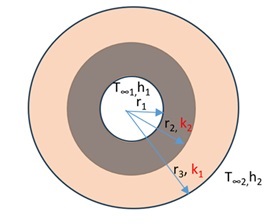
Case 2
Keep all the parameters the same as in case 1, just interchange the insulation sequence, as shown in the below picture:
Apply the values in the thermal resistance formula
Rconv,1 = 1/ (80x 2 x π x 0.1 x 1) = 1/50.24 = 0.02
Rcyl1 = ln (r2/r1) / 2 x π x L x k1 = ln (0.15/0.1) / (2 x 3.14 x 1 x 0.10) = 0.405 / 0.628 = 0.65
Rcyl2 = ln (r3/r2) / 2 x π x L x k2 = ln (0.2/0.15) / (2 x 3.14 x 1 x 0.05) = 0.288 / 0.314 = 0.93
Rconv,2 = 1/ h2 x A = 1/ h2 x 2 x π x r3 x L = 1/ (10x 2 x π x 0.2 x 1) = 1/12.56 = 0.08
Total thermal resistance Rtotal = 0.02 + 0.65+ 0.93+ 0.08
= 1.68 m2.K/W
Overall heat transfer co-efficient U =1/Rtotal
= 1 / 1.68
= 0.6 W/ m2.K
Heat Transfer rate, per unit surface area Q = (T∞1-T∞2)/Rtotal
Q = 10/1.68
Q = 5.95 Watts/m2
Summary:
| Sl. No | Description | Case 1 | Case 2 |
| 1 | Insulation sequence from the inner surface and its thermal conductivity in W/m.K | First layer: k1 = 0.05, Second layer: k2 = 0.1 | First layer: k2 = 0.1, Second layer: k1 = 0.05 |
| 2 | Total thermal resistance in m2.K/W | 1.85 | 1.68 |
| 3 | Overall heat transfer co-efficient in W/m2.K | 0.54 | 0.6 |
| 4 | Heat transfer rate in W/m2 | 5.4 | 5.95 |
Conclusion:
For curved surfaces such as piping, even when insulation thickness, temperature, and convective heat transfer coefficients remain constant, the order of materials with differing thermal conductivities significantly affects heat transfer resistance. In particular, an arrangement where the first layer is composed of a low thermal conductivity material (0.05 W/m·K, Case 1) provides superior resistance to heat transfer compared to a setup where a higher thermal conductivity material (0.1 W/m·K) is used as the initial layer. This is because placing the low-conductivity material closer to the heat source minimizes the initial transfer of heat, effectively creating a stronger barrier against thermal flow.
4. References
- Carrier HAP Software, “Wall”, for Inside and Outside Surface Resistance (Converted to inside and outside convective heat transfer coefficient (h) by taking the reciprocal)
- Textbook: Thermodynamics, Yunus A. Cengel and Michale A. Boles
5. Abbreviations
| DBT | Dry Bulb Temperature |
| HAP | Hourly Analysis Program |
| HVAC | Heating, Ventilation, and Air Conditioning |