1. Introduction
Sand Trap Louvers (STLs) are important components in HVAC fresh air intake systems, especially in regions (like Saudi Arabia, UAE, Iraq, Qatar, Oman, Bahrain, Iran, etc.) where sand, dust, and debris are prevalent in the atmospheric air.
STLs play a vital role in ensuring air quality and protecting the main filters of HVAC equipment.
Proper design and selection of STLs can significantly enhance the efficiency and longevity of the FAHUs/AHU filter systems, intake ductworks and its components.
Note that the purpose of the STLs is to reduce the loading of the larger particle on the main filters of AHUs/FAHUs and to improve its longevity. STLs cannot be used as a replacement to the AHU/FAHU filters.
This article delves into the details of STLs working principle, sizing, key considerations for selection, and practical insights for their application.
2. Construction features of Sand Trap Louver
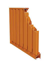
The basic construction of STLs includes the following components:
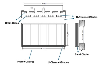
- Outer frames that hold the blades
- Inverted two sets of inverted U-channels (blades) mounted vertically on two opposite rows, fixed to the frames. Different models of STL has different blade width (Normally 100 mm, 130 mm, 150 mm) and different spacing (25, 40 mm) between them.
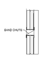
- The sand chute at the bottom side, a plate (sloped sometimes) that makes the collected sands/dust/debris move towards drain holes
- Drain holes, multiple drain holes that drain out the collected sand/dust/debris.
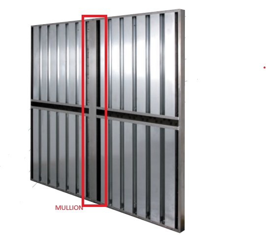
- Mullion (in the larger sizes, the intermediate support member is required to give strength to the structure)
3. Operation Principles
The separation of sand particles or dust from an air stream occurs through three primary steps:
3.1 Creation of Centrifugal Force
The initial stage of separation involves generating centrifugal force.
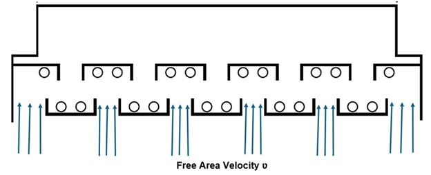
STLs are composed of two sets of vertically mounted inverted U-channels positioned on opposite rows.
The ventilation fan or fan within the Air Handling Unit (AHU) or Fresh Air Handling Unit (FAHU) system creates a negative pressure, causing ambient air containing sand and dust particles to be drawn toward the entire Sand Trap Louvers (STLs) face at a horizontal linear velocity (V, is called face area velocity). Refer to below plan view of STLs.
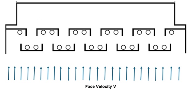
As the U-blades at the front side block the air movement, the air gets diverted to flow through the space between two adjacent U-blades. This velocity (ʋ) is called free area velocity. Refer to below plan view of STLs.
These U-channels convert the incoming air’s linear motion into angular motion, thereby generating a centrifugal force expressed as:
FC = m x r x ω2
Where:
FC = Centrifugal force
m = mass of the particle
r = the path radius
ω = angular velocity
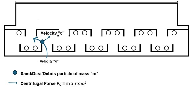
Since FC is directly proportional to the mass for a given path radius and angular velocity, heavier particles (with greater mass) are forced outward toward the U-channels, away from the center of the airflow path.
3.2 Impingement and Momentum Loss
In this second stage, particles moving with a horizontal linear velocity (ʋ) possess momentum given by:
Momentum =m x ʋ
When these sand particles collide with the U-channels, they lose their horizontal momentum.
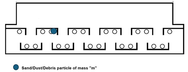
The impact causes a significant reduction in particle velocity, facilitating their separation from the air stream.
3.3 Gravitational Force
Following momentum loss, the particles are subjected to gravitational force (Fg = m x g). They move downward along the vertical surfaces of the U-channels and eventually collect in the bottom sand chute. Note that based on the particle size, the single particle may move downward or so many collected particles will stick to each other till it gets bigger mass then move downwards.
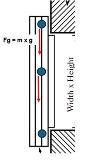
These collected particles are then disposed of through bottom-side openings.
4. Available Shapes and Size Restrictions
STLs are available in rectangular and square shapes.
The standard STLs comes with size restrictions, refer to below tables (from two different manufacturers) for the restriction on the single piece SLT. Other manufacturers may have different maximum size. So please check with manufacturer and plan the STL’s size accordingly.
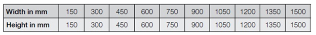
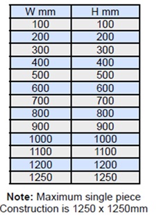
Any combination of width and height is normally possible with in the maximum specified size (Manufacturer 1: 1500 x 1500 mm, Manufacturer 2 : 1250 x 1250 mm).
Even though the sizes are with the increment of 100 or 150 mm, based on the project requirements non-standard sizes are also possible.
For bigger size STLs (Say above 1500 x 1500 mm), mullion is used to connect the smaller sizes and make bigger sizes. The size of 6 m x 6 m STL is also available. The STL placed on the top side will have sand chute as shown in below picture.
Based on space availability, and aesthetic consideration the designer should select the STL’s shape and size.
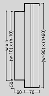
Also to note that the STL sizes are defined by the neck sizes (W x H), through which the air flow is happening. The outer size (W1 x H1) of the STLs is normally about 200 mm bigger on each width and height sides. The designer should be aware of the difference between the neck size and the outer size and should use the outer sizes for space planning.
5. Type
Normally STLs come with three types, namely duct mounted, wall mounted and flush mounted.
Based on the louver location, aesthetic and non-obstruction to material handling movement, the designer should select the appropriate louver type for his application
6. Material Construction
STLs are often exposed to harsh outdoor environmental conditions. Common materials used include:
- Aluminum: Lightweight, corrosion-resistant, and suitable for most applications.
- Galvanized Steel: Offers robust protection in industrial settings.
- Stainless Steel: Ideal for highly corrosive environments (Offshore, seashore and plants emits corrosive gases)
- Product Colors
Standard natural colors of aluminum, Stainless Steel, and Galvanized Iron.
Most of the manufacturers provide STLs in different RAL Colours, as per the project requirement to meet the architectural aesthetic requirements.
7. Options
STLs come with the following options.
- Wire mesh, to stop the ingress of bigger size items (like insects, papers etc.)
- Filters, to increase the particle removal efficiency
- Damper (Manual and motorized), for regulation, to provide minimum ventilation, and isolation
- Combination of all
Based on the project requirements, the designer should select the appropriate STLs and its options.
9. Sand Trap Louver (STL) Sizing
The following design parameters should be considered while sizing the STLs:
- Design airflow rate (Q)
- Face velocity (V) /free area velocity (ʋ)
- Particle separation effectiveness (%)
- Pressure drops (ΔP)
- Space restrictions
The steps to be followed for STL sizing and selection is given below:
Step 1: Obtain/take the design fresh airflow rate (Q) from the ventilation rate calculations.
Step 2: Check the project design basis/concept design documents for the design restrictions (maximum free area velocity/face velocity, maximum allowable pressure loss) and the minimum separation effectiveness (Vs particle size range) requirement.
Step 3: For a given airflow rate (Q) and maximum free area velocity/face area velocity (Step 2), from the manufacturer ΔP vs Velocity curve (for a specified particle size range), check the actual pressure drop is not exceeding the design restriction value. If it is within the limit go to step four.
If the ΔP is more than the set limit, then reduce the velocity and check ΔP. Repeat the step till the ΔP is within the allowable design limit.
Step 4: Calculate the free area or face area required (by using the formula “Flow area = Flow rate /Velocity).
From the manufacturer catalogue for “Free area to STL Size table”, calculate the required STL size.
Note that most of the manufacturers have specified free area velocity as the selection basis, however few manufacturers has specified face velocity as the selection basis. In below Sample, the sizing based on free area velocity has been considered.
10. SAMPLE PROJECT
For a given below design parameters, select the Sand Trap Louver (STL):
- Design airflow rate = 5000 CFM
- Max. allowable pressure drop = 0.1 in. W.G
- Max. free area velocity = 500 FPM (2.5 m/s)
- Required minimum effectiveness = 45 % (for the particle size range of 76 to 699 µm)
As the design flow rate, velocity and pressure loss restriction is already specified, directly go to STEP-3.
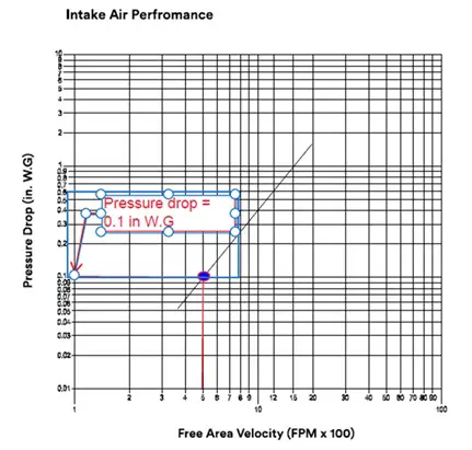
Below ΔP, effectiveness graphs are for a particular model (Blade width, spacing between blade) type. So, for each model the graph will be different. Also to note that, the ΔP value is normally for the basic model (without any optional items like wire mesh, damper, filter), so for the actual pressure drop for the STLs with other optional items included, the designer shall coordinate with the manufacturer.
From the below manufacturer performance curve, for a given free area velocity (500 FPM), the pressure drop is 0.1 in W.G, which is with in the allowable pressure loss of 0.2 in W.G. So the free velocity 500 FPM is meeting the design pressure loss limit.
From the below manufacturer curve for the particle size range of 76 to 699 µm, the effective of the louver is about 50 %, which is higher than the requirement of 45 %, so the selected model is meeting the design requirement.
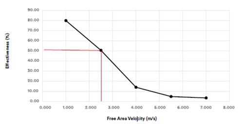
Note that reducing the free area velocity will reduce the pressure drop (ΔP) and increases the effectiveness (%).
So repeat this STEP-3, by reducing the free area velocity, till the design criteria values (Maximum ΔP, minimum effectiveness) are met.
STEP-4
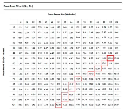
Required free area (Sq. ft) = Airflow rate (Q, ft3/min) / Free area velocity (ʋ, ft/min)
= 5000 / 500
= 10 Sq.ft
From the manufacturer provided chart below, the minimum size (and shape, outer frame width and height in inches) required to meet the minimum design requirements are highlighted in the red boxes. If there is no space constraint in the project, then higher sizes (any size right side to the red box) can be selected which will reduce the ΔP and will increase the sand separation effectiveness. However, note that increasing the size will results in increase in initial cost and issues related to support system design (wind effect) issues of bigger size louvers
11. Design Free Area Velocity and Face Velocity
If there is NO design inputs (velocity, pressure loss, and separation effectiveness) values are available in the Employer specifications/design documents, then the following velocity can be used.
- Face velocity = 1 m/s (maximum)
- Free area velocity = 2.5 m/s to 3 m/s (maximum)
If there are no restrictions on the available space and initial cost of the project, the above velocities can be halved so that the pressure loss and separation efficiency improved further.
If there is a space restriction, then above velocity values
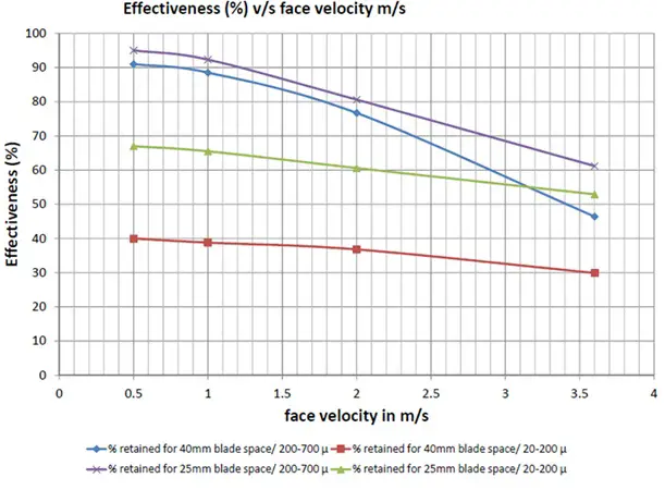
12. Effect of Blace Spacing on Pressure Loss and Effectiveness
Refer below the manufacturer graph (Face velocity based) for the effect of blade spacing on pressure loss and separation effectiveness.
Pressure Drop
Reducing the blade spacing increases the pressure drop.
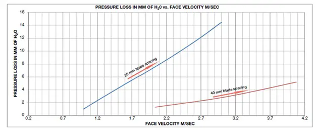
Separation Effectiveness
Reducing the blade spacing increases the separation effectiveness.
13. Compliance with Standards
Some projects may demand for compliance to relevant standards and certifications, such as AMCA 500-L-12 (Air Movement and Control Association) for performance and quality.
14. Applications of Sand Trap Louvers
- Industrial Facilities
- Commercial Buildings
- Offshore Installations
- Power Plants
- Data Centers
15. Installation Guidelines
Proper installation ensures optimal performance of sand trap louvers:
- Sealant: Use weather-resistant sealants to prevent air leakage around the louver frame.
- Clearance: Provide adequate clearance around the louver for filter removal, maintenance and debris removal.
16. Maintenance of Sand Trap Louvers
Regular maintenance prolongs the life and efficiency of STLs:
- Inspection: Periodically inspect for sand accumulation and structural damage.
- Cleaning: Remove debris from the collection chamber and blades using air or water jets.
- Corrosion Protection: Check for signs of corrosion and reapply protective coatings as needed.
- Drainage Check: Ensure drain holes and collection chambers are free of blockages.
17.Advantages of Sand Trap Louvers
- Stable operation: In the absence of Self-Draining Type Filters (STLs), larger particles must be captured by Air Handling Unit (AHU) or Fresh Air Handling Unit (FAHU) filters. Since AHU and FAHU filters are not self-draining, accumulated particles gradually increase the pressure drop across the system. This heightened pressure places additional strain on AHU/FAHU fans, leading to a reduced supply airflow rate. As a result, system performance deteriorates, adversely affecting room cooling, ventilation, and pressurization.
- Enhanced Air Quality: Filters out large particles, ensuring clean air for indoor ventilated spaces.
- Reduced Equipment Wear: Protects HVAC intake ductwork components and ventilation fans from abrasive particles.
- Energy Efficiency: Low-pressure drop designs reduce energy consumption.
- Cost Savings: Minimizes maintenance costs associated with frequent replacement of AHU/FAHU filters and damaged components due to abrasion.
18. Conclusion
Sand Trap Louvers (STLs) are indispensable for HVAC systems in dust-prone environments, offering essential protection for AHU/FAHU filters, intake ductwork, and ventilation equipment. Proper design, selection, and sizing of STLs ensure enhanced air filtration, energy efficiency, and extended equipment lifespan.
This comprehensive guide has explored key aspects of STL construction, operational principles, sizing strategies, material options, and maintenance best practices. By understanding these critical factors, HVAC designers and facility managers can make informed decisions to optimize system performance and reduce maintenance costs.
As environmental challenges grow in arid regions, the role of STLs becomes increasingly significant in safeguarding HVAC systems and maintaining air quality in industrial, commercial, and residential applications. Selecting the right STL configuration tailored to project requirements is not just a technical necessity but a strategic investment in long-term system efficiency and operational stability.
19. References
- ASHRAE Handbook—Fundamentals
- ASHRAE Handbook—HVAC Systems and Equipment
- ASHRAE 62.1 Ventilation and Acceptable Indoor Air Quality
- AMCA 500-L-12- Laboratory Methods of Testing Louvers for Rating
20. Abbreviations
| AHU | Air Handling Unit |
| AMCA | Air Movement and Control Associations |
| ASHRAE | American Society of Heating, Refrigerating, and Air-Conditioning Engineers |
| CFM | Cubic Feet per Minute |
| FAHU | Fresh Air Handling Units |
| HVAC | Heating, Ventilation, and Air Conditioning |
| STL | Sand Trap Louver |
| UAE | United Arab Emirates |
| WG | Water Gauge |