1. Introduction
In HVAC cooling applications, a chilled water-cooled system is normally used for large-scale buildings where the total cooling load is substantial, the number of terminal units is extensive, and the distance between the outdoor unit and indoor air terminal units is significant.
Due to their efficiency and scalability, chilled water systems are well-suited for high-capacity cooling requirements in residential, commercial, industrial, and institutional facilities.
2. Components of a Chilled Water System
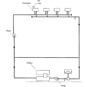
A chilled water system is composed of several critical components, including:
Terminal units
These include Fan Coil Units (FCUs, Air Handling Units (AHUs), and Fresh Air Handling Units (FAHUs), which are responsible for delivering conditioned air to indoor spaces.
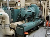
Chillers
Chillers are critical components of the chilled water system, designed to remove the heat from the hot chilled water return from the terminal units (AHUs, FCUs, FAHUs) and supply the cold chilled water back to the terminal units.
Chillers are available in either water-cooled or air-cooled configurations.
Piping System
This network transports chilled water between the chiller plant and terminal units. It includes various inline components such as valves, strainers, and balancing devices to regulate flow and maintain system efficiency.
Chilled Water Pumps
The chilled water pumps are essential for circulating chilled water through the piping network, ensuring that cooled water reaches all terminal units and returns to the chiller for re-cooling.
Refer to the accompanying schematic diagram for an overview of the chilled water system components (Courtesy: Handbook of Air Conditioning and Refrigeration by Shan K. Wang).
3. Chiller Plant Cooling Load
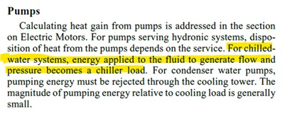
When determining the cooling load of the chiller plant evaporator, it is common practice to sum the peak cooling loads of the terminal equipment and apply a suitable diversity factor to account for the simultaneous peak load. However, this calculation often overlooks the load contribution from the chilled water CHW pumps.
The CHW pump absorbed load must also be accounted for to accurately determine the total evaporator cooling load (Refer to the extract from the ASHRAE Handbook, Fundamental, Chapter Nonresidential Cooling and Heating Load Calculations). Neglecting this factor can lead to undersized chiller equipment and operational inefficiencies.
The pump load typically accounts for 1.5% to 3% of the total building cooling load.
This can be understood through the following calculations:
Calculated total cooling load (L) = 1000 kW (Assumed)
CHW In/Out temperatures to Chiller = 12 OC / 6 OC (ΔT = 6 OC)
The specific heat capacity of CHW (Cp) = 4.187 kJ/kg.K.
Density of chilled water (ρ) = 1000 kg/m3
The chilled water mass flow rate (m) = L / (Cp x ΔT)
= 1000 / ((12-6) x 4.187))
= 39.8 kg/s
The chilled water volume flow rate (q) = 0.0398 m3/s
Normally pressure loss in the system = 2.5 to 5 bar (i.e., 300,000 to 500,000 Pa)
Pump efficiency ηp = 65% (Assumed)
Pump absorbed power P (kW) = Flow (in m3/s) x pressure loss (in kPa, kN/m2) / ηp (Refer to Important Note, Section 4)
= 0.0398 x Pressure loss (kPa) / 0.65
Pump absorbed power P (kW) = 0.0612 x Pressure loss (kPa),
| Sl. No | Description | Pressure loss | |||||
| 2.5 bar (= 250 kPa) | 3 bar (= 300 kPa) | 3.5 bar (= 350 kPa) | 4 bar (= 400 kPa) | 4.5 bar (= 450 kPa) | 5 bar (= 500 kPa) | ||
| 1 | Pump absorbed power (P), in kW | 15.31 | 18.34 | 21.43 | 24.5 | 27.55 | 30.61 |
| 2 | Building Load (L), kW | 1000 | 1000 | 1000 | 1000 | 1000 | 1000 |
| 3 | *Pump load in % of Building Termina load | 1.5 | 1.8 | 2.1 | 2.5 | 2.8 | 3.1 |
| 4 | Total Plant load TPL (= L + P), in kW | 1015.31 | 1018.34 | 1021.43 | 1024.5 | 1027.55 | 1030.61 |
| 5 | *This % of the load (kW value specified in Sl. No 1) should be added to the total building load (L) to arrive at the total chiller plant cooling load (TPL). | ||||||
4. Important Note
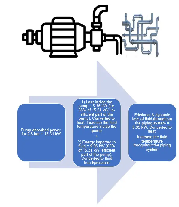
Pump Inefficiency and Heat Generation
A significant portion of the power absorbed by the pump is converted into heat, which directly affects the chilled water (CHW) system’s performance:
- In this scenario, 35% of the pump absorbed power, which represents the inefficiency of the pump, is directly converted into heat within the pump itself. This heat transfer leads to an increase in the CHW temperature as the energy dissipates into the circulating water.
- The remaining 65% of the pump absorbed power, which is the efficiency part, is initially converted into mechanical energy to generate pressure and flow in the CHW system. However, as the chilled water circulates through the piping network and terminal equipment, this energy also eventually converts into heat due to frictional and dynamic losses within the system.
- These combined losses result in the total pump input power being entirely converted into heat, contributing to the overall load on the chilled water system.
5. Conclusion:
Since all the pump’s input power ultimately translates into heat, it must be accounted for in the total cooling load calculation of the chiller’s evaporator. Beyond the cooling loads from the building’s terminal equipment (e.g., AHUs, FCUs, FAHUs), the pump’s absorbed power load must be added to determine the total evaporator cooling load.
Neglecting this additional load can lead to undersized chillers and reduced system efficiency, as the cooling capacity may be insufficient to offset the combined building and pump-induced heat loads.
By understanding this critical relationship, HVAC professionals can design and operate systems more effectively, achieving better energy efficiency and system reliability.
6. References
ASHRAE Handbook – Fundamental, Chapter “Nonresidential Cooling and Heating Load Calculations”
7. Abbreviations
| AHU | Air Handling Unit |
| ASHRAE | American Society of Heating, Refrigerating, and Air-Conditioning Engineers |
| CHW | Chilled Water |
| CHWP | Chilled Water Pump |
| FAHU | Fresh Air Handling Unit |
| FCU | Fan Coil Unit |
| HVAC | Heating, Ventilation, and Air Conditioning |
| TPL | Total Plant Load |